Please see room Bannan 218 for parts not listed.
Capacitor | Crystal | Hobby | Linear | Logic | Microprocessor | Optoelectronic | Oscillator
Overcurrent Protection | Potentiometer-Trimmer | Resistor | SMDCodes | SMD Socket Adapters
Test Clips | Transistor-FET | Thermal Heat Sink
An overcurrent event or fault is when the current (amperage) in an electrical circuit exceeds the rated capacity. There are many possible sources for an overcurrent fault such as a short, power cross, surge, etc. These faults can permanently damage the follow-on electronics and may cause serious injury.
Aavid Applications Engineering Support
Aavid Thermalloy engineers can assist with the design of heat sinks for both forced and natural convection applications. Frequently we have already encountered a situation similar to yours and may have a solution readily available. If not, we will start from scratch and help you design a cooling strategy uniquely tailored for your application. www.aavidthermalloy.com
Need to find a part? Try these search engines for parts or try the online distributors listed below.

Keep up to date on the latest technology & design news - Free magazine subscriptions!
|
74ls00c224 Quad 2 input NAND gate |
74ls85a3e6 4 bit magnitude comparator |
741763316 Decade Counter |
|
74ls014aba Quad 2 input NAND gate (OC) |
74ls863e01 Quad 2 input XOR gate |
741763316Binary Counter |
|
74ls02f56e Quad 2 input NOR gate |
74ls90092e Decade counter |
74ls191d1e4 4 bit binary up / down counter |
|
74ls035b67 Quad 2 input NAND gate (OC) |
74LS91 8-bit shift register |
74ls192690d BCD up / down counter |
|
74ls04505f Hex Inverter |
74ls90092e Divide by 12 counter |
74ls192690d 4 bit binary up / down counter |
|
74ls05ecc6 Hex Inverter (OC) |
74ls90092e 4-bit Binary counter |
74ls195ebfd 4 bit shift register |
|
74ls066457 Hex Inverter buffer/driver |
74ls95da42 4-bit shift register |
74ls19679b9 Presettable decade counter |
|
74ls08eb48 Quad 2 input AND |
74ls1072c09 Dual JK flip-flops with clear |
74ls19679b9 Presettable binary counter |
|
74ls0961a1 Quad 2 input AND gate (OC) |
74ls1094a62 Dual JK pos edge trig flip flop |
74199 8-bit shift register |
|
74ls103cf7 Triple 3 input NAND gate |
74ls112c884 Dual JK neg edge trig flip flop |
74ls2211bdb Dual monostable multivibrator |
|
74ls111b94 Triple 3 input AND gate |
741217bd2 Monostable multivibrator |
74s225d730 16x5 FIFO memory |
|
74ls129d48 Triple 3 input NAND gate (OC) |
74ls1231d89 Retriggerable Monostable multivibrator |
74ls240fdd2 Octal buffer/line driver |
|
74ls1308c8 Dual 4-input NAND gate Schmitt trigger |
74ls1231d89 Retriggerable Monostable multivibrator |
74ls2413040 Octal 3-state buffer |
|
74ls14cff4 Hex Inverter Schmitt trigger |
74ls12576fe Quad 3-state Buffer |
74ls240fdd2 Octal buffer/line driver |
|
74ls153314 Triple 3 input AND gate (OC) |
74ls132dc34 Quad 2 input NAND gate Schmitt trigger |
74ls2458a9d Octal bus transceiver |
|
74ls164b63 Hex Inverter (OC) |
74ls133d5c7 13 input NAND |
74ls2517bfc Data selector / MUX |
|
74LS20 Dual 4 input NAND gate |
74ls13656d0 Quad 2 input XOR (O.C) |
74ls2578e23 Quad 2 input mux 3-state |
|
74ls21590f Dual 4 input AND gate |
74ls138f9da 3-to-8 line decoder/demux |
74ls2595194 8 bit addressable latch |
|
74ls2263b6 Dual 4 input NAND gate (OC) |
74ls13969bd Dual 1-of-4 decoder/demux |
74ls2664e75 Quad 2 input XNOR (O.C) |
|
7425fec4 Dual 4 input NOR gate with strobe |
74ls138f9da 10 line - 4 line octal priority encoder |
74ls2736608 Octal D type flip flop with clear |
|
74ls278351 Triple 3 input NOR gate |
74ls138f9da 8 line - 3 line octal priority encoder |
74ls2803836 9 bit odd / even parity generator |
|
7425fec4 8 input NAND gate |
74150e6fc Data selector/mux |
74ls298d54b Quad 2 input MUX with storage |
|
74ls329bf4 Quad 2 input OR gate |
74ls1516d03 8 input MUX |
74ls299a5ff 8 bit universal shift register |
|
74ls387b99 Quad 2 input NAND gate Buffer (OC) |
74ls1533494 Dual 4-to-1 Multiplexer |
74ls3231687 8-Bit Shift register |
|
74ls42b427 BCD to DEC decoder |
74ls1545606 4-to16 decoder/demux |
74ls367749c Hex bus driver |
|
7445ec4e BCD to DEC decoder |
74ls15502c0 Dual 2 line to 4 line decoder / demux |
74ls367749c Hex bus driver with invereters |
|
74ls472c1d BCD to 7 seg decoder/driver (OC) |
74ls15502c0 Dual 2 line to 4 line decoder / demux (O.C) |
74ls373bbae Octal transparent latch |
|
74ls4804d2 BCD to 7 seg decoder/driver (OC) |
74ls1570797 Quad 2 input MUX |
74ls373bbae Octal D type flip flop 3-state |
|
74ls51049a AND/OR/INVERT gate |
74ls1570797 Quad 2 input MUX with invereted outputs |
74ls39042d4 Dual 4 bit decade counter |
|
74ls54c552 4-wide AND/OR/INVERT gate |
74ls1609042 BCD decade counter |
74ls393ba36 Dual 4 bit binary counter |
|
74F64 Pos 4-2-3-2 input AND/OR/INVERT gate |
74ls1611432 Synchronous 4 bit binary counter |
74ls3955a71 4 bit shift register |
|
7470a48b JK flip flop |
74ls162d21a BCD decade counter |
74ls5404cc0 Octal buffer 3-state |
|
7472ac65 JK M/S flip flop |
74ls1611432 Asynchronous 4 bit binary counter |
74ls5404cc0 Octal buffer 3-state outputs |
|
74ls73e711 Dual JK flip flop with clear |
74ls164e63f 8 bit SIPO shift register |
|
|
74ls74b7dc Dual D-Type flip-flops with preset and clear |
74ls1657c21 8 bit PISO shift register |
|
|
74ls756fbe 4 bit bi-stable latch |
74ls166ee58 8 bit PISO shift register |
|
|
74ls76b646 Dual JK flip-flops with preset and clear |
74ls1743432 Hex D type flip flop with clear |
|
|
74ls83b778 4 bit full adder |
74ls1743432 Quad D type flip flop with clear |
EDN microprocessor/microcontroller directory
PIC16F84A3fcb Datasheet Get Started with your first PIC program
|
55549f7 Timer / Oscillator
|
LM741e968 Op-Amp
|
uaf42985d Universal Active Filter
|
| PN2222A-NPN77c0 NPN Transistor | 2N3904NPN51b1 NPN Transistor | 2N3906PNP082d PNP Transistor |
| mpq222210c1 NPN Transistor | MPQ2907A-QUAD-PNP4910 PNP Transistor | 2N3819 JFETdeb3 JFET |
|
NDP6060L5503 |
NDP6020P6240 |
ISD1700h40f9 Single Chip Voice Record and Playback.
More similar products-datasheets | other fab
This is a very basic hobby project and can take less than an hour.
LED Polarity
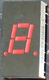
7-Segment Display
Other reference: http://en.wikipedia.org/wiki/Seven-segment_display
.gif)
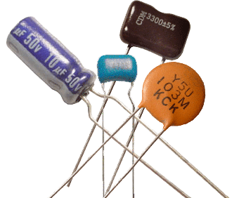
Polarized Capacitors
WARNING
REVERSE POLARITY OF ELECTROLYTIC & TANTALUM CAPACITORS CAN CAUSE
FIRE & EXPLOSION
Capacitors having a value of about 0.47 micro-farad or greater are often Electrolytic or Tantalum (polarized) types. This means that it is very important how they are connected. Polarized capacitors are almost always marked with the polarity on the body of the component. If the two capacitor leads are of different lengths then the longer of the two is usually the + (positive) terminal. Only non-polarized capacitors may be fitted to the breadboard or PCB either way, in the same way as resistors.
Surest way to damage an electrolytic capacitor is to reverse polarity at working voltage, self-destruction will occur and violent.
Use safety glasses and keep eyes and body parts away when applying power for the first time to a circuit that includes polarized capacitors. Discard any damaged parts.
IMPORTANT: Capacitors with values below 100 pf may be marked two ways: Either with just two digits (22 pF = "22") or three digits (22 pF = "220",). In the latter case the third digit signifies the number of zeros following the first two digits. "220" = 22 pF, "221" = 220 pF, "222" = 2200 pF.
| VALUE | MARKING | VALUE | MARKING | VALUE | MARKING |
|---|---|---|---|---|---|
| 1pf; 3pf; 5pf | 1; 3; 5 |
2.7, 3 or 3.3 pF can be interchanged with each other. 4.7 or 5 pF can be interchanged with each other. |
2.7, 3 or 3.3 pF can be interchanged with each other. 4.7 or 5 pF can be interchanged with each other. |
2.7, 3 or 3.3 pF can be interchanged with each other. 4.7 or 5 pF can be interchanged with each other. |
2.7, 3 or 3.3 pF can be interchanged with each other. 4.7 or 5 pF can be interchanged with each other. |
| 10 pf | 10or 100 | 0.001 uF | 102 | 0.10 uF | 104 |
| 12 pf | 12or 120 | 0.0012uF (1200pf) | 122 | 0.12 uF | 124 |
| 15 pf | 15or 150 | 0.0015uF | 152 | 0.15 uf | 154 |
| 18or 180 | 0.0018 uF (1800pf) | 182 | 0.18 uF | 184 | |
| 22 pf | 22or 220 | 0.0022uF | 222 | 0.22 uF | 224 |
| 27 pf | 27or 270 | 0.0027uF | 272 | 0.27 uF | 274 |
| 33 pf | 33or 330 | 0.0033 uF | 332 | 0.33 uF | 334 |
| 39 pf | 39or 390 | 0.0039uF | 392 | 0.39 uF | 394 |
| 47 pf | 47or 470 | 0.0047uF | 472 | 0.47 uF | 474 |
| 58 pf | 58or 580 | 0.0056uF | 562 | 0.56 uF | 564 |
| 68 pf |
68or 680 |
0.0068uF | 682 | 0.68 uF | 684 |
| 82 pf | 82or 820 | 0.0082uF | 822 | 0.82 uF | 824 |
| 100 pf | 101 | 0.01 uF | 103 | 1uF | 105 or 1uf |
| 120 pf | 121 | 0.012 uF | 123 | ||
| 150 pf | 151 | 0.015 uF | 153 | ||
| 180 pf | 181 | 0.018 uF | 183 | ||
| 220 pf | 221 | 0.022 uF | 223 | ||
| 270 pf | 271 | 0.027 uF | 273 | ||
| 330 pf | 331 | 0.033 uF | 333 | ||
| 390 pf | 391 | 0.039 uF | 393 | ||
| 470 pf | 471 | 0.047 uF | 473 | ||
| 560 pf | 561 | 0.056 uF | 563 | ||
| 680 pf | 681 | 0.068 uF | 683 | ||
| 820 pf | 821 | 0.082 uF | 823 |
References: http://en.wikipedia.org/wiki/Resistors
Through-Hole Resistors
Four-color-band axial resistors
Main article: Electronic color code
Four-band identification is the most commonly used color coding scheme on all resistors. It consists of four colored bands that are painted around the body of the resistor. The scheme is simple: The first two numbers are the first two significant digits of the resistance value, the third is a multiplier, and the fourth is the tolerance of the value. Each color corresponds to a certain number, shown in the chart below. The tolerance for a 4-band resistor will be 1%, 5%, or 10%
5-color-band axial resistors
5-band identification is used for higher precision (lower tolerance) resistors (1%, 0.5%, 0.25%, 0.1%), to notate the extra digit. The first three bands represent the significant digits, the fourth is the multiplier, and the fifth is the tolerance. 5-band standard tolerance resistors are sometimes encountered, generally on older or specialized resistors. They can be identified by noting a standard tolerance color in the 4th band. The 5th band in this case is the temperature coefficient
SMT resistors
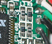
This image shows two surface mount resistors
Surface mounted resistors are printed with numerical values in a code related to that used on axial resistors. Standard-tolerance Surface Mount Technology (SMT) resistors are marked with a three-digit code, in which the first two digits are the first two significant digits of the value and the third digit is the power of ten (the number of zeroes).
For example:
"334" = 33 × 10,000 ohms = 330 kiloohms
"222" = 22 × 100 ohms = 2.2 kiloohms
"473" = 47 × 1,000 ohms = 47 kiloohms
"105" = 10 × 100,000 ohms = 1 megaohm
Resistances less than 100 ohms are written: 100, 220, 470. The final zero represents ten to the power zero, which is 1. For example:
"100" = 10 × 1 ohm = 10 ohms
"220" = 22 × 1 ohm = 22 ohms
Sometimes these values are marked as "10" or "22" to prevent a mistake.
Resistances less than 10 ohms have 'R' to indicate the position of the decimal point (radix point). For example: "R003" = 0.003 ohms. This is very small value, generally used in current sense applications.
"4R7" = 4.7 ohms
"0R22" = 0.22 ohms
"0R01" = 0.01 ohms
Precision resistors are marked with a four-digit code, in which the first three digits are the significant figures and the fourth is the power of ten. For example:
"1001" = 100 × 10 ohms = 1 kiloohm
"4992" = 499 × 100 ohms = 49.9 kiloohm
"1000" = 100 × 1 ohm = 100 ohms
"0", "000", and "0000" sometimes appear as values on surface-mount zero-ohm links, since these have (approximately) zero resistance.
References: http://en.wikipedia.org/wiki/Potentiometer
References: http://en.wikipedia.org/wiki/Crystal_oscillator
Manufactures: www.foxonline.com | www.ecsxtal.com
Crystals

Oscillators
: http://embedeo.com/smd_codes/